 English
 中文
中文 Magyarország
 Україна
 Polska
 Россия
 T ürkiye
 日本語
日本語 Deutsch


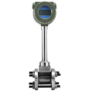
ProductIntroduction
Steam vortex flowmeter (also known as vortex street flowmeter) is mainly used for measuring the flow of industrial pipeline media fluid, such as gases, liquids, vapors and other media. It is characterized by low pressure loss, wide range and high accuracy. It is almost not affected by parameters such as fluid density, pressure, temperature, viscosity and so on. There are no movable parts, so the reliability is high and the maintenance quantity is small. Instrument parameters can be stable for a long time. The vortex flowmeter adopts piezoelectric stress sensor, which has high reliability and can work in the working temperature range of -20 to +250 C. It has analog standard signal and digital pulse signal output. It is easy to match with computer and other digital systems. It is an advanced and ideal flow meter.
In the fluid, a triangular columnar vortex generator is generated, and a regular vortex is generated alternately from both sides of the vortex generator. The vortex is called Carmen vortex. As shown in the right picture, the vortex is arranged asymmetrically in the downstream of the vortex generator 1.
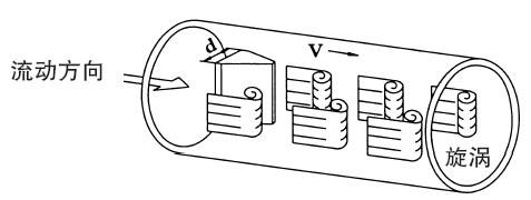
Table 1, liquid and gas (unit: m) Three /h)
Path (DN) | Liquid flow range (M Three /h) | Output frequency range (Hz) | Gas flow range (M Three /h) | Output frequency range (Hz) |
Fifteen | 1.2 to 6.2 | 90~900 | 5~25 | 265~2640 |
Twenty | 1.5 to 10 | 40~396 | 8~50 | 218~1982 |
Twenty-five | 1.6 to 16 | 32~325 | 10~70 | 172~1420 |
Thirty-two | 2~20 | 20~250 | 15~150 | 130~1350 |
Forty | 2.5 to 25 | 13~130 | 22~220 | 115~1147 |
Fifty | 3.5 to 35 | 9~93 | 36~320 | 96~854 |
Sixty-five | 6~60 | 8~82 | 50~480 | 61~583 |
Eighty | 10~100 | 6~65 | 70~640 | 45~417 |
One hundred | 15~150 | 5~50 | 130~1100 | 43~367 |
One hundred and twenty-five | 25~250 | 5~47 | 200~1700 | 33~290 |
One hundred and fifty | 40~400 | 4~40 | 280~2240 | 27~221 |
Two hundred | 80~800 | 3~33 | 580~4960 | 24~207 |
Two hundred and fifty | 140~1400 | 3~26 | 970~8000 | 20~171 |
Three hundred | 200~2000 | 2~22 | 1380~11000 | 17~136 |
Four. Outline size drawing
Path (DN) | L (mm) | H (mm) | 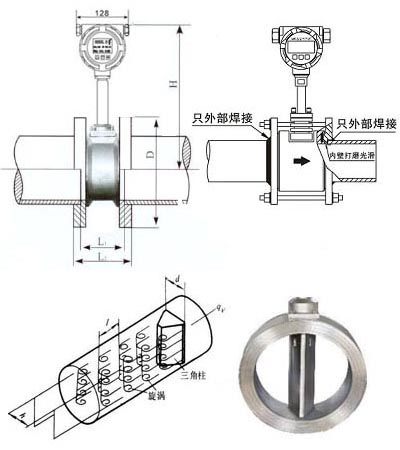 | |||||||||
Ten | Sixty-six | Three hundred and sixty | ||||||||||
Fifteen | Sixty-six | Three hundred and sixty | ||||||||||
Twenty | Sixty-six | Three hundred and sixty | ||||||||||
Twenty-five | Sixty-six | Three hundred and sixty | ||||||||||
Thirty-two | Sixty-six | Three hundred and sixty-five | ||||||||||
Forty | Eighty | Three hundred and seventy | ||||||||||
Fifty | Eighty | Three hundred and seventy-five | ||||||||||
Sixty-five | Ninety-three | Three hundred and eighty-three | ||||||||||
Eighty | One hundred | Three hundred and ninety | ||||||||||
One hundred | One hundred and twenty-five | Four hundred | ||||||||||
One hundred and twenty-five | One hundred and forty-five | Four hundred and seventy | ||||||||||
One hundred and fifty | One hundred and sixty-five | Five hundred | ||||||||||
Two hundred | One hundred and ninety-six | Five hundred and eighty | ||||||||||
Two hundred and fifty | Two hundred and thirty-five | Six hundred and fifty | ||||||||||
Three hundred | Two hundred and fifty-five | Seven hundred | ||||||||||
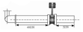
Five, installation sketch map | ||||||||||||
Matters needing attention | Legend | |||||||||||
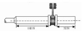
1. installation of expansion pipe For small diameter and large flow, it is necessary to expand the pipe and ensure that the front straight section of the flowmeter is more than 15D, and the straight pipe section is more than 5D. | | |||||||||||
2. installation of shrinkage tube For large diameter and small flow, it is necessary to install the shrink tube while ensuring that the front straight section of the flowmeter is more than 15D, and the straight pipe section is more than 5D. | | |||||||||||
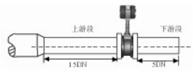
3. installation of elbow pipe If the front end of the flowmeter has a 90 degree elbow or a T type joint, ensure that the straight straight section of the flowmeter is equal to or equal to 15D, and the straight pipe section is equal to or equal to 5D. | | |||||||||||
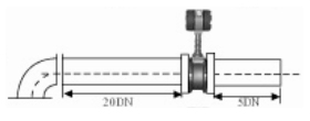
4. installation of two bends on the same plane. If the front end of the flowmeter has two 90 degree elbows, ensure that the front straight section of the flowmeter is more than 20D, and the straight pipe section is more than 5D. | | |||||||||||
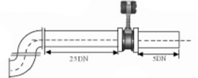
5. installation of two curved pipes in different planes If the front end of the flowmeter has two 90 degree elbows, ensure that the front straight section of the flowmeter is more than 25D, and the straight pipe section is more than 5D. | | |||||||||||
6. installation of regulating valve If the regulator is needed before and after the flowmeter, ensure that the front straight section of the flowmeter is more than 25D, and the straight pipe section is more than 5D. | 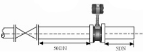 | |||||||||||
L six, product selection form | ||||||||||||
ZM-LUGB | Steam vortex flowmeter | |||||||||||
caliber (mm) | Ten | DN10~DN50 (flange type, clamp type, threaded type, pair clip type) | ||||||||||
Fifty | DN50~DN150 (pair clamp, flange type) | |||||||||||
One hundred | DN100~DN300 (flange type, pair clip type) | |||||||||||
Three hundred | DN300 above is inserted. | |||||||||||
Installation mode | B | Pair clamp | ||||||||||
L | Flange connection type | |||||||||||
C | Insertion type | |||||||||||
Compensation mode | nothing | No compensation | ||||||||||
BC | Temperature and pressure compensation | |||||||||||
W | Single temperature compensation | |||||||||||
Y | Single pressure compensation | |||||||||||
Measuring medium | Y | liquid | ||||||||||
Q | Gas | |||||||||||
Z | steam | |||||||||||
temperature range | T1 | Normal temperature (below 120 C) | ||||||||||
T2 | High temperature type (below 250 C) | |||||||||||
Pressure grade | P1 | Atmospheric pressure to 1.6MPa | ||||||||||
P2 | 2.5MPa | |||||||||||
P3 | 4.0MPa | |||||||||||
Material of Ontology | A | carbon steel | ||||||||||
B | 304 stainless steel | |||||||||||
C | 316 stainless steel | |||||||||||
Power supply mode | D | Two wire DC24V 4 to 20mA | ||||||||||
H | Two wire DC24V 4 to 20mA+HART protocol | |||||||||||
C | Battery powered | |||||||||||
Additional options | R | RS485 MODBUS protocol | ||||||||||
M | Pulse output | |||||||||||
B | Explosion protection (ExII CT6) | |||||||||||
SendInquiry