1. Product Overview
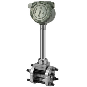
The clamp type vortex flowmeter can widely measure the flow of gas, liquid and steam in the medium and small diameter pipes of various trades. The body has its own connecting flange. When connecting with the pipeline, the flange of the flow meter is connected with the flange of the pipeline, and then fastened by bolts. Its characteristics are simple structure and convenient installation.
Two, technical parameters
1, measuring medium: liquid, general gas, natural gas, steam (saturated steam and superheated steam);
2. The possible range of measurement: Reynolds number is 5 x 10³~7 * 106
3. Normal measurement range: Reynolds number is 2 x 10⁴~7 * 106
4. Measuring velocity range: liquid 0.5 ~ 7m/s gas 4 ~ 35mm/s steam 7 ~ 70m/s
5. The measured fluid temperature is from -40 to +300 C.
6. Measured fluid temperature: 1.6, 4, 25MPa
7, accuracy: 1, 1.5, 0.5 (through the nonlinear finishing can reach 0.5).
8, repeatability: 0.2% of the indication value;
9, body material: ICr18Ni9Ti;
10, pressure loss: Delta =1.2 * r * V2 * 10-6 formula: Delta P- pressure loss r- measured fluid density (Kg/m3) v- tube mean velocity (m/s)
11. Ambient temperature: -20 C ~ +55 C (special requirement)
12. Ambient humidity: less than 90%RH
13. Atmospheric pressure: 86-106KPa
14, external power supply: 3.6 ~ 224VDC
15, internal power supply: 3 ~ 4.5VVDDC
16, work power supply: 80/A
17, working voltage: 2.7 ~ 3.6V
18, working frequency: 0.1 ~ 3000H
19, signal distant transmission distance: 100mm
20, signal output: pulse output (external power supply) current output 4 to 20mADC (two wire system for 24VDC power supply) pulse output and current output can only choose one way.
Three, flow range table
Table 1, liquid and gas (unit: m) Three /h)
Path (DN) | Liquid flow range (M Three /h) | Output frequency range (Hz) | Gas flow range (M Three /h) | Output frequency range (Hz) |
Fifteen | 1.2 to 6.2 | 90~900 | 5~25 | 265~2640 |
Twenty | 1.5 to 10 | 40~396 | 8~50 | 218~1982 |
Twenty-five | 1.6 to 16 | 32~325 | 10~70 | 172~1420 |
Thirty-two | 2~20 | 20~250 | 15~150 | 130~1350 |
Forty | 2.5 to 25 | 13~130 | 22~220 | 115~1147 |
Fifty | 3.5 to 35 | 9~93 | 36~320 | 96~854 |
Sixty-five | 6~60 | 8~82 | 50~480 | 61~583 |
Eighty | 10~100 | 6~65 | 70~640 | 45~417 |
One hundred | 15~150 | 5~50 | 130~1100 | 43~367 |
One hundred and twenty-five | 25~250 | 5~47 | 200~1700 | 33~290 |
One hundred and fifty | 40~400 | 4~40 | 280~2240 | 27~221 |
Two hundred | 80~800 | 3~33 | 580~4960 | 24~207 |
Two hundred and fifty | 140~1400 | 3~26 | 970~8000 | 20~171 |
Three hundred | 200~2000 | 2~22 | 1380~11000 | 17~136 |
Four, installation skills
1, try to avoid strong electrical equipment, high frequency equipment and strong switching power supply equipment. The power supply of the meter can be separated from these devices as far as possible.
2, avoid the direct influence of high temperature heat sources and radiation sources. If installation is necessary, there must be insulation and ventilation measures.
3, avoid high humidity environment and strong corrosive gas environment. Ventilation is necessary if it is to be installed.
4. Vortex flow meters should be avoided as far as possible. If it is necessary to install, the pipeline fastening device should be installed at the upstream and downstream 2D, and the vibration pad should be added to enhance the anti vibration effect.
5. The instrument should be installed indoors. It should be waterproof when installed. It should be noted that the cable should be bent into U shape at the electrical interface to prevent water from entering the amplifier housing along the cable.
6, there should be plenty of space around the instrument installation point for installation wiring and regular maintenance.
 English
 中文
中文 Magyarország
 Україна
 Polska
 Россия
 T ürkiye
 日本語
日本語 Deutsch